Midterm: A Glove-Controlled Airship
The Airship Glove Controller with accelerometer:
A Glove-Controlled Airship:
We began with a radio-controlled toy blimp straight out of the box:


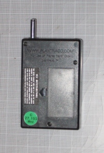
There are three basic components: the balloon, the gondola, and the hand-held radio controller.


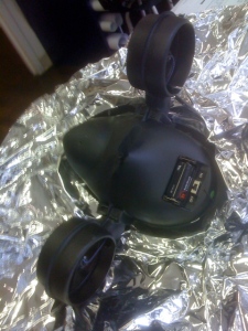

A word of warning: The balloon and radio controller are pretty durable, but the gondola, built for speed, is of the thinnest plastic. Treat it very gently. You will see this one begin to sport electrical tape patches as time goes on. Here are a few grainy close-ups:


There are two circuit boards: one in the hand-held controller, and one in the gondola. For the Midterm, we hacked into the controller, but left the gondola board alone. For the Final, we sidelined both boards, and developed our own.
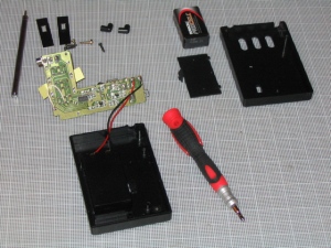
The first step was to figure out how the controller did what it did, and what alternatives we had. So, taking it apart:


Pretty simple–a circuit board, 3 switches, a battery case and an antenna.

Ground runs around the perimeter. The switch posts are to the left, and each switch has 3 pairs of legs–pairs I am assuming for stability. Powering the front pair (left here) turns the propellors forward, and the rear pairs (right here) in reverse.
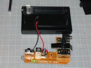

The serial port gave us a brief hopeful moment: the idea that we might be able to send simple serial commands from the Arduino was tantalizing. Without the communication protocol, however, it would be like trying to set up a call with a satellite long since dead, or better yet, a stone. We reached out to Plantraco to see if they would share their protocol with us, but to no avail.
Abandoning that approach, we tried a simple end-run around the switches. Their posts were easy to sort out on the back side of the circuit board, as was ground, and it was a fairly easy matter to fire the fans directly from a battery with alligator clips. The next step was to do this with the Arduino:

The post-it marks the starboard fan. Once we had succeeded in powering one fan, we moved on to controlling each of them. We quickly resorted to the nautical terminology of port and starboard as “left fan forward, right fan reverse” became cumbersome. Here we diagrammed out the Arduino controls we needed to program:

And our initial excitement when we first got a fan not simply powered, but also controlled by the Arduino. Here it is pulsing one fan:
And here the Arduino is controlling two synchronized fan motors:
Upon reflection, I can see that while it worked, what we were doing was slightly wonky. If you look at the photo above and the videos, you can see that we have grounded the board, and are giving it 5V. That was necessary for the radio control. We were then directly powering individual switches from the Arduino out pins. Effectively, that means there were 2+ positive leads coming to the board and one common ground. Not necessarily a problem, and given that the circuit was used to 9V anyway, probably not serious here. However, introducing additional voltage past a regulator was definitely a possibility in this arrangement, as was the chance of frying something.
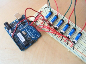
Rory suggested that we separate the signal voltage from the power voltage with a circuit of reed switches:
